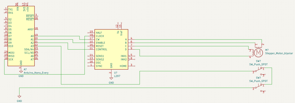
Picture this: you’re in the lab at 3 am and you’re trying to figure why your Arduino code is stopping your stepper motor without hitting the limit switch. You measure the signal with a multi meter and can see no sign of the the signal being pulled high. You switch from using the internal pull up resistor to an external to see if the length of the cable is to much for the Arduino. Convinced it must be an issue with your code you implement a “de-bounce” method for the button press surly that would solve the problem, right? However, the problem persists.
You decide to print out the analog values to serial and you notice the voltage is dropping according as seen by the Arduino. You take the Arduino and connect a voltage source but that reads fine without the random voltage drops. How could this be? Why does the signal seem to change when its inside the control box vs being outside?
Finally in a fit of rage you pull out your $28,400 Tectonics MSO580B. And what you see is this:
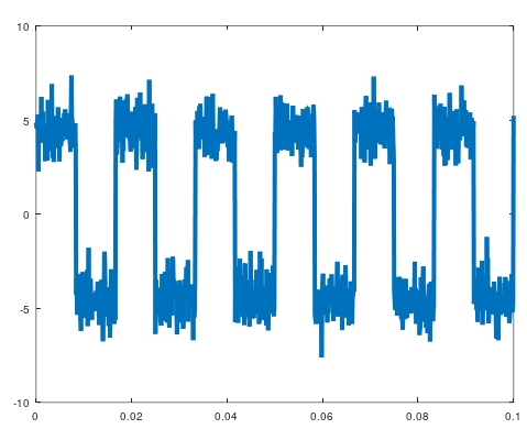
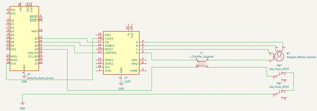
But wait that signal isn’t connected to that wire and it dawns on you! Parallel wires carrying AC or PWM signals act as inductors!
What you just experienced was the pain of signal noise or cross talk and it can be one of the most frustrating things an electrical engineer will encounter.
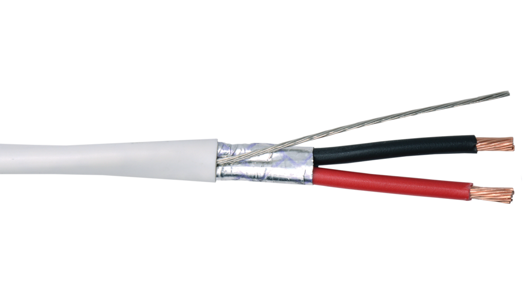
So whats the solution? Get a shielded cable and move the limit switch signals outside the stepper motor driver cable. The cable shield should be grounded to the same ground as the Arduino. Also ensure the leads inside the control box are not close/touching for long runs.